Now that we have our RGB data isolated, we can start creating our plugin.
To start creating a plugin, we are going to open a text editor and paste in the text below.
export function Name() { return ""; }export function VendorId() { return ; }export function ProductId() { return ; }export function Publisher() { return ""; }export function Documentation(){ return "troubleshooting/brand"; }export function Size() { return [1,1]; }export function ControllableParameters() { return [ {"property":"shutdownColor", "group":"lighting", "label":"Shutdown Color", "min":"0", "max":"360", "type":"color", "default":"009bde"}, {"property":"LightingMode", "group":"lighting", "label":"Lighting Mode", "type":"combobox", "values":["Canvas", "Forced"], "default":"Canvas"}, {"property":"forcedColor", "group":"lighting", "label":"Forced Color", "min":"0", "max":"360", "type":"color", "default":"009bde"}, ];}export function Initialize() {}var vLedNames = [ "Led 1" ]; var vLedPositions = [ [0,0] ];export function LedNames() {}export function LedPositions() {}export function Render() {}export function Shutdown() {}function hexToRgb(hex) { let result = /^#?([a-f\d]{2})([a-f\d]{2})([a-f\d]{2})$/i.exec(hex); let colors = []; colors[0] = parseInt(result[1], 16); colors[1] = parseInt(result[2], 16); colors[2] = parseInt(result[3], 16); return colors;}export function Validate(endpoint) { return endpoint.interface === 0 && endpoint.usage === 0 && endpoint.usage_page === 0;}export function ImageUrl() { return "";}The above text is a basic layout for a device plugin.
We will start by filling in the fields in the top of the plugin with information for our device.
We can fill in the name field with the device's name.
Finding Vendor and Product IDs
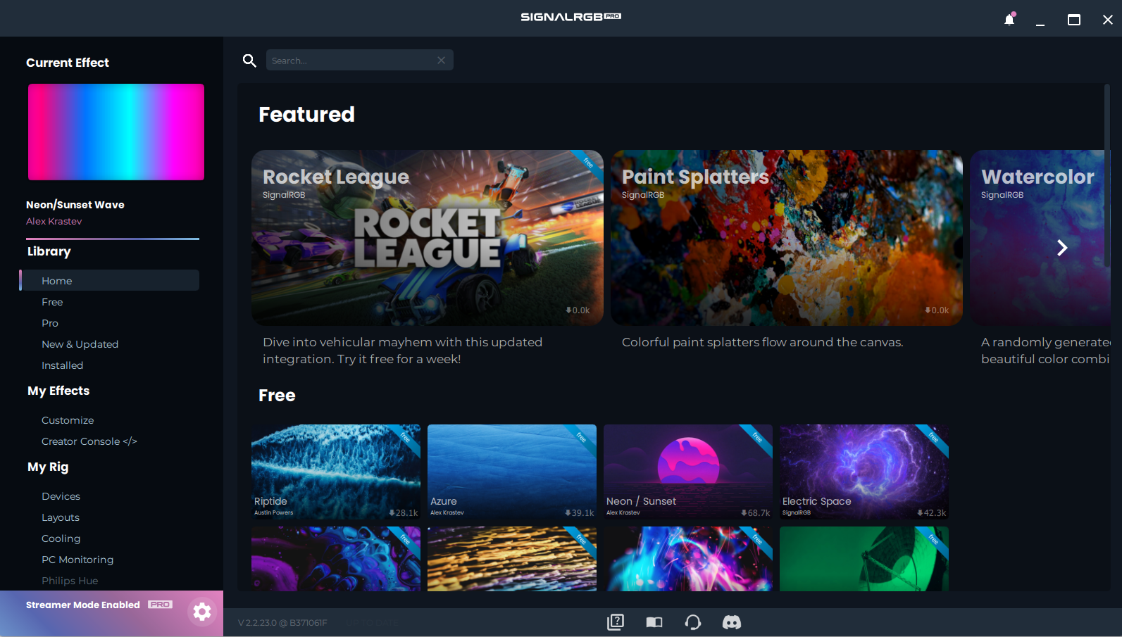
To Find the Vendor ID and Product ID, we need to first open SignalRGB's settings menu by using the cog icon in the bottom left corner.
Now, we need to go down to the Device Information page.
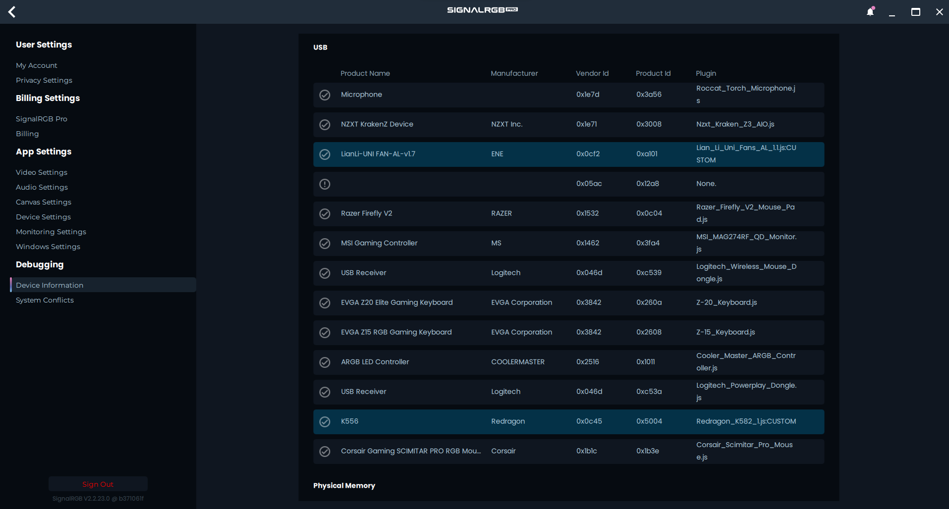
We are looking for the VendorID and the ProductID for the device that we are implementing. In my case, this is the Corsair Scimitar Pro. The Scimitar's Vendor ID is 0x1b1c and its Product ID is 0x1b3e.
Now that we have the Vendor and Product ID, we can fill those fields in on the plugin.
To fill in the Publisher field, you can put your name!
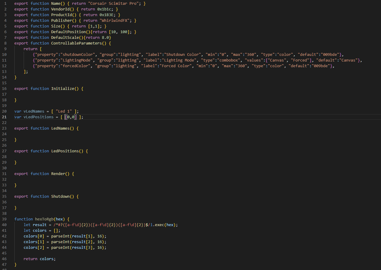
Now, we have filled in all of the fields that we can for the moment.
Here is our example for the Scimitar Pro with the fields filled in.
Creating an RGB Packet
Next, we need to create a function to send color data to our device. We will start by creating a simple function like the one below:
function sendColors(shutdown = false){ let packet = [];}Next, we need to start filling in our packet with some data, which we will do by using the data from one of our marked RGB packets.
- NOTE: This device is zero-padded. This means that we need to shift all of our bytes up 1 position. Learn about zero padding here.
function sendColors(shutdown = false){ let packet = []; packet[0] = 0x00; packet[1] = 0x07; packet[2] = 0x22; packet[3] = 0x05; packet[4] = 0x01; }We start filling in the header data for the packet as shown above. We stop at position 4, since position 5 is our first byte of RGB related data.
Determining Packet Type
Next, we need to create our color filling system. There are a few different ways that this can be done. The method that is used depends on the packet structure of the device. Here are a few different color packet examples:
function sendZone(zone, shutdown = false){}function SendPacket(shutdown = false){}function sendColors(shutdown = false){}The three above examples are each suitable for a different packet structure. The sendZone function is good for devices that use a separate packet for each LED. The sendPacket function is more suitable for devices that send multiple LEDs in a row within a single packet. The sendColors function is suitable for devices that have multiple LEDs in a packet, but they are not one directly after the other. In our case, we are going to use the sendColors function.
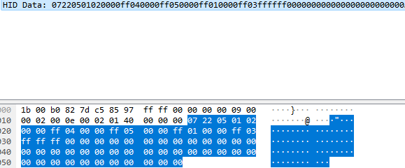
function sendColors(shutdown = false){ let packet = []; packet[0] = 0x00; packet[1] = 0x07; packet[2] = 0x22; packet[3] = 0x05; packet[4] = 0x01; let zoneId = [2, 4, 5, 1, 3]; for(let zone_idx = 0; zone_idx < vLedPositions.length; zone_idx++) { let iX = vLedPositions[zone_idx][0]; let iY = vLedPositions[zone_idx][1]; var col; if(shutdown){ col = hexToRgb(shutdownColor); }else if (LightingMode === "Forced") { col = hexToRgb(forcedColor); }else{ col = device.color(iX, iY); } packet[(zone_idx * 1) + 2] = zoneId[zone_idx]; packet[(zone_idx * 1) + 3] = col[0]; packet[(zone_idx * 1) + 4] = col[1]; packet[(zone_idx * 1) + 5] = col[2]; } packet[21] = 0xff; packet[22] = 0xff; packet[23] = 0xff; device.write(packet, 120);}To properly set up the sendColors function, we need to figure out the Zone ID's for our device. Looking at the packet capture again, we see that the order of zones appears to be 2,4,5,1,3 as shown below. Notice that we added a 5th zone as it looks like we can address the DPI LED as well.
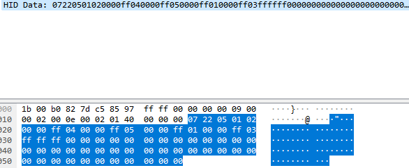
Now that we figured out our Zone ID's, we need to figure out our offsets for our zone_idx. Our first zone is at packet[4], and our second one is at packet[8]. This means that our zone_idx needs to be multiplied by 4 each time to get to a new LED. We also need to figure out how many positions we shift the RGB data. Since our first zone is at packet[5], we just need to offset our packet by 5 bytes, as seen below.
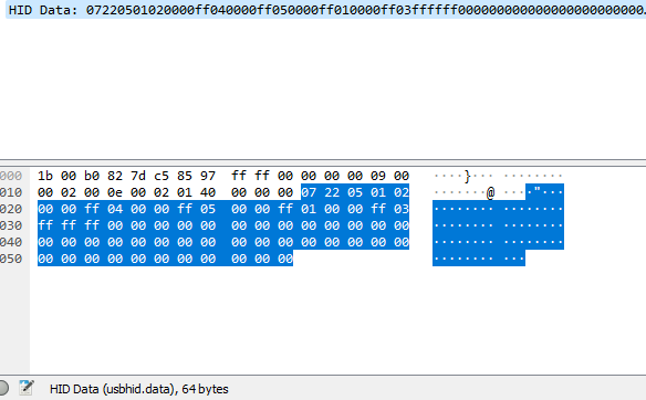
function sendColors(shutdown = false){ let packet = []; packet[0] = 0x00; packet[1] = 0x07; packet[2] = 0x22; packet[3] = 0x05; packet[4] = 0x01; let zoneId = [2, 4, 5, 1, 3]; for(let zone_idx = 0; zone_idx < vLedPositions.length; zone_idx++) { let iX = vLedPositions[zone_idx][0]; let iY = vLedPositions[zone_idx][1]; var col; if(shutdown){ col = hexToRgb(shutdownColor); }else if (LightingMode === "Forced") { col = hexToRgb(forcedColor); }else{ col = device.color(iX, iY); } packet[(zone_idx * 4) + 5] = zoneId[zone_idx]; packet[(zone_idx * 4) + 6] = col[0]; packet[(zone_idx * 4) + 7] = col[1]; packet[(zone_idx * 4) + 8] = col[2]; } device.write(packet, 120);}Now that we added everything that needs to go into our packet, we need to find our packet length. To find the packet length, we just need to see how long our data from Wireshark is. Looking at our example, we can see that the data is 64 bytes long in this case.
- NOTE: This device is zero-padded, which means we need to make the write length one longer than it is in the Wireshark capture.
Now that we know the length of our data, we just need to set our device.write length to 65 bytes long, as shown below.
function sendColors(shutdown = false){ let packet = []; packet[0] = 0x00; packet[1] = 0x07; packet[2] = 0x22; packet[3] = 0x05; packet[4] = 0x01; let zoneId = [2, 4, 5, 1, 3]; for(let zone_idx = 0; zone_idx < vLedPositions.length; zone_idx++) { let iX = vLedPositions[zone_idx][0]; let iY = vLedPositions[zone_idx][1]; var col; if(shutdown){ col = hexToRgb(shutdownColor); }else if (LightingMode === "Forced") { col = hexToRgb(forcedColor); }else{ col = device.color(iX, iY); } packet[(zone_idx * 4) + 5] = zoneId[zone_idx]; packet[(zone_idx * 4) + 6] = col[0]; packet[(zone_idx * 4) + 7] = col[1]; packet[(zone_idx * 4) + 8] = col[2]; } device.write(packet, 65);}Now that we have our RGB packet set up, we need to set up our LEDs and choose our device endpoints.
Basic LED Setup
To setup our LEDs, we need to add the correct number of LEDs to our vLedNames and our vLedPositions. In our case, we need to add four more LEDs to each, as shown below.
var vLedNames = [ "Led 1", "Led 2", "Led 3", "Led 4", "Led 5" ]; var vLedPositions = [ [0,0], [1,0], [2,0], [3,0], [4,0] ];We are giving these four LEDs basic mappings for now as we do not know where these LEDs are located physically on our device with respect to their mappings inside of SignalRGB.
Now that we have mapped out our LEDs, we need to set our device size. Our device size needs to be one larger than our furthest out LED in both directions. In my case, the size needs to be [5,1], as our furthest LED is at [4,0].
export function Name() { return "Corsair Scimitar Pro"; }export function VendorId() { return 0x1b1c; }export function ProductId() { return 0x1B3E; }export function Publisher() { return "WhirlwindFX"; }export function Documentation(){ return "troubleshooting/corsair"; }export function Size() { return [5,1]; }The next thing we need to figure out is our device's endpoint.